General
What is the CubeSat Kit designed to do?
The CubeSat Kit is designed to help you complete a successful CubeSat mission in as short a time as possible, and at low cost. Each CubeSat Kit includes:
- A rugged Development Board that you use in the lab to prototype mission-specific hardware, develop software, test your ideas, measure performance, etc.
- Software libraries and the Salvo RTOS to simplify software development
- A low-mass, high-strength Flight Model with a large useable surface are and interior volume that fully conforms to the CubeSat specification
- Your choice of powerful and low-power PPM processors to perform multiple duties (e.g. COMM and CD&H) in your CubeSat
- Drop-in support for popular transceivers
- Desktop power supplies
- Additional development tools (e.g. a USB interface that can also power theCubeSat)
How much does a CubeSat Kit cost?
CubeSat Kits are available in a variety of configurations. Please see the Pumpkin price list for more information.
How quickly can I get a CubeSat Kit?
CubeSat Kits and components are normally available for immediate delivery.
What do I have to add to the CubeSat Kit to turn it into a functional satellite that's ready for launch?
At a minimum, you'll need to add a power source (i.e. an EPS with batteries, solar cells, etc.), and your payload / experiment. You'll want to add a transceiver and an antenna if you plan to communicate with your CubeSat. Plus, you'll need to program the PPM processor to run your CubeSat and handle communications, etc.
Why are antennae, solar cells, etc. not included in the CubeSat Kit?
The design of items like antennas and power-supplies is very mission-oriented, and should be tailored to each individual CubeSat. The CubeSat Kit is a general-purpose kit, and is designed to satisfy the basic requirements of the CubeSat specifications.
With the CubeSat Kit, you don’t have to worry about building a sturdy yet light enclosure, adding Remove-Before-Flight and Launch Switches, creating a working connector scheme, picking a microcontroller, etc. We've done all of that for you!
Does the CubeSat Kit include a radio (transceiver)?
No, but you use one from Microhard Systems off-the shelf, plug it into the Motherboard, add an antenna and you're ready to begin sending and receiving. Or you can use one from MaxStream via a CubeSat Kit Modem Adapter. These transceivers can be purchased directly from Pumpkin.
I prefer to use / design my own radio. Will that work in the CubeSat Kit?
Yes. The CubeSat Kit can be configured in various ways. You can put your own radio in the CubeSat Kit. Or you can use a CubeSat Kit Modem Adapter to use alternate radios.
Do I have to create my own Printed Circuit Boards (PCBs) in order to use this CubeSat Kit?
Not necessarily, but realistically you will need to develop at least one PCB that is specific to your CubeSat mission. For simple designs, you can use the Motherboard's powerful MCU as your primary controller. You can put your own electronics (serial EEPROMs, sensors, power supply, connectors, etc.) on a CubeSat Kit Protoboard and connect them via the CubeSat Kit Bus connectors.
Sophisticated users with complex designs will want to build their own modules on custom PCBs. Again, these will connect to the PPM processor via the CubeSat System Bus connectors. User modules can also connect to the PC/104 bus, or even the PC/104-Plus bus.
Why is the PCB mounting scheme of the CubeSat Kit designed around the PC/104 mechanical specifications?
First, the PC/104 specification has a simple, pass-through connector scheme that is well-suited to the tight confines of the CubeSat. The CubeSat System Bus connector is the same as the standard PC/104 stackthrough connector, a well-established industry standard.
Second, many potential CubeSat developers want to run sophisticated applications on their CubeSats that they can first develop on PCs. By accommodating +5V-only PC/104 modules, the CubeSat Kit supports x86-class single-board computers (SBCs) in the PC/104 form factor like the Diamond Systems (http://www.diamondsystems.com/) Prometheus SBC, which was used in the successful QuakeSat project (http://www.quakefinder.com/quakesat.htm), and Lippert's CoolRunner Lite 2, a more modern board that has been used in SSDL's BioLaunch missions. Naturally, other PC/104 modules can also be used in the CubeSat Kit.
Third, the mechanical layout of PC/104 modules leaves a considerable percentage of the total PCB area available for circuitry.
What equipment do I need to program the PPM processor?
All you need beyond the CubeSat kit is a PC with a USB port and a CubeSat-Kit certified C compiler / Integrated Development Environment (IDE). You use the compiler and IDE to develop software for this MCU.
The CubeSat Kit contains all of the hardware required to connect a PC to the Development Board and the PPM processor for downloading, programming and debugging.
Each CubeSat Kit also includes a project license for the Salvo Pro RTOS on the Development Board and Motherboard, and a custom version of HCC-Embedded's EFFS-THIN FAT file system for use with SD cards on the CubeSat Kit.
My PC / laptop doesn't have a parallel port. What Should I do?
As of July 2007 all CubeSat Kits ship with USB-based Flash Emulation Tools / Debuggers. Therefore a parallel port is no longer required on the PC.
What's the difference between the Development Board and the Motherboard?
The Development Board is on a much larger PCB to facilitate access to the various systems on-board. It also includes provisions for multiple power supply sources, and jumpers to isolate parts on the system. It also includes some additional circuitry not available on the Motherboard (e.g. +5V and +3.3V regulators, indicator LEDs, and an RS-232 port). Electrically, the Motherboard is a subset of the Development Board.
Assembly / Mechanical
What is the CubeSat Kit structure made of?
The materials used in the CubeSat Kit are as follows:
- The structure (chassis, cover plate and base plate) are made from 5052-H32 sheet aluminum, in thicknesses appropriate for each individual part.
- Machined components (e.g. the feet, spacers and Mid-plane Standoffs) are made from 6061-T6 aluminum.
- All captive and loose fasteners and the Remove-before-Flight Pin are made from stainless steel.
- The male/female threaded standoffs supplied for development and prototyping are made from plated brass.
- Printed circuit boards (PCBs) are double- or multilayer designs using FR4 material.
See the data sheets for individual components (e.g. switches, ICs, etc.) for the materials used in their construction.
Is the CubeSat Kit an inch or metric design?
All of the user-serviceable fasteners are metric. Relevant user dimensions are usually presented in metric units, but some are in SAE / inch units.
Is the CubeSat Kit structure hard-anodized?
All surfaces that come in contact with the CubeSat launcher are hard-anodized to prevent galling. Hard-anodizing is an insulating process. In order to provide the shielding of a Faraday-cage, the remaining surfaces of the CubeSat Kit are gold alodyned to maintain electrical conductivity.
Why is there an oval cutout on the front face of the CubeSat Kit?
This cutout enables the MHX transceiver to fit within the confines of the CubeSat's 10x10x10 cm size. If you use the MHX transceiver, you'll find that this cutout leaves enough room to attach your antenna cable to the MHX transceiver. If you don’t use the MHX transceiver, you can put solar cells over the cutout, run other wires in and out of the CubeSat there, etc.
It doesn’t look like I can fit all of my payload into a 10x10x10cm CubeSat Kit. Are larger CubeSat Kits available?
Yes, 10x10x5cm (0.5U), 10x10x15cm (1.5U), 10x10x20cm(2U) and 10x10x30cm(3U) CubeSat Kits are available. They are identical to the 10x10x10cm (1U) CubeSat Kit except for their Chassis Walls Assemblies, which are correspondingly shorter or longer.
Environment
What temperature range is the CubeSat Kit designed for?
All of the parts in the CubeSat kit that are destined for space operate over the –40 C to +85 C industrial temperature range. The SD/MMC cards used for mass storage are typically specified over -20 C to +65 C. SD/MMC cards for the industrial temperature range are available at additional cost.
What kinds of glues and/or epoxies are used in the CubeSat Kit?
All of the components in the CubeSat Kit are permanently riveted, positively fastened with machine screws, or soldered to the Motherboard. Users may choose to employ space-grade adhesives as they see fit.
What kind of wiring does the CubeSat Kit have?
The only wires in the CubeSat Kit connect the Remove-Before-Flight and Deployment Switches to the Motherboard or to user circuitry, and these are furnished by the user. All other inter-board interconnects are done with 0.100" (2.54mm) spacing headers.
Payload
My CubeSat payload is very flat. Can I put it on a PC/104 card?
Very likely. If you design your payload to fit inside a PC/104 module's form factor, you can stack it along with the other user modules and PC/104 modules in your CubeSat.
My CubeSat payload measures 5x5x5cm. Can the CubeSat Kit accommodate it?
Yes. With only the Motherboard + PPM in place, there's plenty of room for large payloads. You may want to consider mounting any user modules against the side walls of the CubeSat Kit.
How can I run wires from a module to the top surface of the CubeSat Kit (the one where the Motherboard is mounted)?
There is a 4.7mm slot between the front edge of the Motherboard and the CubeSat inner wall, and a 3mm slot between the rear edge and the Motherboard. To reach that surface from inside the CubeSat (e.g. to wire solar cells), route your wires through that slot.
The allowable height on Slot 5 is only 6mm. What is Slot 5 good for?
Slot 5 is immediately below the CubeSat Kit's bottom cover. Therefore it's an ideal location to place sensors that must be exposed to space, e.g. a miniature camera lens. Just cut a hole in the bottom cover that's large enough for the camera lens to pass through, and ensure that it does not violate the CubeSat's allowable external dimensions.
Electronics
How much power does a PPM processor take?
Each PPM processor has sleep and idle modes. At full speed, [1] a Motherboard with PPM A1 should consume no more than 20mA @ +3.3V (66mW). By taking advantage of the each PPM's power-saving design and the event-driven Salvo RTOS, the average current can drop to well below 1mA (3.3mW).
Why is a linear regulator used to generate VCC? I thought switchers are more efficient.
A low-dropout (LDO) linear regulator was chosen for this application primarily because it requires fewer parts (thus enhancing reliability and reducing weight) than most switchers, and the PPM processor's power consumption is so low that the overall system power savings would be negligible with a switcher.
If your CubeSat already generates a suitable VCC, you can disable and/or disconnect the regulator on the Motherboard and feed it VCC via the CubeSat System Bus connector.
What kinds of electronic components are used in the CubeSat Kit?
Primarily small surface-mount components, like 0805 and 1206 passive packages, and TQFP chip packages.
How much current can the Remove-Before-Flight and Deployment Switches conduct?
They are each rated for 10A. The same switches are used in all CubeSat Kits, regardless of size.
Why are separate signals from the PPM processor used to enable +5V_SW power and the MHX transceiver interface?
This is done primarily for two reasons: 1) The MHX transceiver takes a relatively long time to power up. The –ON_MHX signal allows the PPM processor to keep the MHX transceiver power on while the interface is disabled and the I/O pins are used for other purposes. 2) For CubeSat Kit configurations that employ the PPM processor as the main processor, +5V_SW can be used as a power supply signal that is under the PPM processor's control.
Can I leave the PPM processor on all the time while in orbit?
Theoretically, yes. The power consumption of most PPMs is so small (especially in its power-saving modes) that you can probably leave it on all the time.
How do I manage power consumption in the CubeSat Kit?
The biggest drain on your power supplies is likely to be your transceiver (radio), especially when transmitting. The PPM processor can control power to the MHX transceiver, so that it only consumes power when the PPM processor is ready to transmit data.
Does the CubeSat Kit include a power supply?
Yes. Both 5V, high-power and 9V external table-top power supplies are included for use witheach CubeSat Kit. The 9V supply is used to power the Development Board. The 5V supply can power the Development Board and can also power an assembled CubeSat through the external power connector.
It is up to you to design or purchase your own electrical power system (EPS) for your CubeSat. This will normally involve solar cells and/or batteries, and may require outputs at multiple voltages (e.g. +3.3V and +5V). CubeSat power supplies are normally tailored to the CubeSat's payload and processor(s).
I want to run Linux in my CubeSat. Is the CubeSat Kit compatible?
Most PPM processors are much too small to run Linux. However, there are many off-the-shelf PC/104 modules with processors that are capable of running Linux. Additionally, there are even smaller single-board Linux computers like those from www.gumstix.com. So, just pick one and put it in your CubeSat Kit.
I plan on running both a PC/104 SBC and the Motherboard's MCU in a dual-processor configuration. How can I interrupt the PPM processor from the SBC?
Check how the –RESET signal from the CubeSat System Bus is routed to the PPM processor. This signal can for example activate the –RST/NMI signal on PPM A1/A2/A3. The MSP430 processor on these PPMs can be configured in software to treat the –RST/NMI signal as a non-maskable interrupt.
Are the '244 interface chips really necessary?
Yes. Without them, the PPM processor could be subjected to overvoltages on its inputs, leading to damage. The type of interface chips and the overall circuit topology has been carefully chosen to eliminate any chance of damage to the PPM processor from the +5V-based USB-to-serial converter and MHX transceiver in any powered or unpowered state. Additionally, the interface chips guarantee the correct logic-level signals when the PPM processor is connected to either interface.
Why does the Development Board have an RS-232 connector?
To facilitate your CubeSat development. For example, you might decide that the easiest way to interface the PPM processor to a PC/104 or PC/104-Plus module with an x86-class processor running Linux is via a serial port. This is advantageous, because RS-232 drivers operate at RS-232 voltage levels, which bypasses the issue of +3.3V to +5V translation. So, You could place your PC/104 module on the Development Board and connect its processor to the PPM processor via this serial port. You would need to eventually design your own RS-232 interface on a user module when you integrate your design into a CubeSat.
The RS-232 driver is not incorporated into the Motherboard because that would unnecessarily constrain the design.
Alternatively, you could use the RS-232 port for printf()-style debugging, and simply ignore it when you integrate your design into a CubeSat.
Communications Interfaces (USB and MHX Transceiver)
How can I use the PPM processor's ADC inputs to sample voltages throughout my CubeSat? They're connected to the USB and MHX transceiver interfaces!
Depending on the PPM you choose, there may or may not be overlap between its ADC inputs and other functions in the CubeSat Kit. For example, some control signals are multiplexed with ADC inputs on PPM A1|A2|A3. On PPM D1 and D2, the ADC inputs are completely separate from the control signals.
You can use most of the PPM processor's analog inputs for voltage sampling because the USB-to-serial converter and the MHX transceiver are normally isolated from the PPM processor's bus. When you want to sample, disable the interfaces, configure the I/O pins as analog inputs, and sample. When you want to connect to either the USB-to-serial converter or the MHX transceiver, configure the I/O pins as digital inputs or outputs, and enable one of the interfaces. The I/O pins that enable the interfaces must always be configured as digital inputs or outputs. All of this can be managed very easily using the Salvo RTOS and basic RTOS concepts.
A few precautions must be taken for this to work properly. You can either selectively isolate your analog sources from the PPM processor bus (e.g. by using an analog switch), or you can buffer the analog sources in a manner that's tolerant of being driven by a digital signal appearing at the I/O pin.
Can I use the PPM processor's second UART to talk to serial devices other than the USB-to-Serial converter and MHX transceiver?
Yes. When neither of these on-board interfaces is enabled, you can talk to other serial devices. You must ensure that when either the USB-to-serial converter or the MHX transceiver is enabled, your other serial devices are disabled (tri-state / hi-Z) on the UART's receive data pin.
Can the PPM processor talk to both the USB-to-serial converter and the MHX transceiver at the same time?
No. Only one interface should be active at the same time. Control of the interfaces is under the PPM processor's control. The USB-to-serial converter is envisioned as an "on the ground" communications link, and the MHX transceiver is envisioned as an "in-flight" communications link. Therefore you would not normally need to have both active at any time.
Why don’t the data and control signal names for the two interfaces match?
They don’t match because one is Data Terminal Equipment (DTE), and the other is Data Communications Equipment (DCE).
What kind of handshaking do the interfaces support?
The USB-to-serial converter interface supports simple hardware handshaking (RTS/CTS), as well as software handshaking (XON/XOFF).
The MHX transceiver supports full hardware handshaking (RTS/CTS, DSR/DTR, DCD), as well as software handshaking.
Can I reset the interfaces?
Yes. Each interface can be reset by the PPM processor.
Can an external processor interface with the USB-to-serial converter?
Generally, no. To move data from an external processor (e.g. a PC/104 SBC) through the USB-to-serial converter will require that the external processor communicate with the PPM processor serving as an intermediary.
Can an external processor interface with the MHX transceiver?
Yes, directly over the CubeSat System Bus. This requires that the external processor apply +5V power to +5V_SW. All of the MHX transceiver's data and control signals except DCD are available on the CubeSat System Bus connectors.
Can I use the USB port in space?
If your USB cable is long enough …
How many CubeSat Kits can I connect to a PC via USB?
The number of CubeSat Kits that can be connected via USB is limited solely by the number of USB ports on your PC.
The USB chip uses almost as much power as the PPM processor! Isn't that wasteful?
The USB interface is designed so that it is only powered when connected to an external host (e.g. a laptop PC). At all other times the USB interface consumes no power.
Why aren't any MHX transceiver status indicators available to the PPM processor or on the CubeSat System Bus connector?
All of the MHX transceiver's status information can be gleaned by reading from its internal registers. Therefore these signals are unnecessary. They are attached to LEDs on the Development Board as a visual aid.
I prefer to use my own radio. How can I integrate it into the CubeSat Kit?
The simplest approach is probably to package your radio in the same form as the MHX transceiver, so that it can be plugged into the MHX transceiver sockets. You can then choose to control the radio from the PPM processor, or externally via the CubeSat System Bus. Note that the MHX transceiver socket is supplied with +5V power from +5V_SW.
Can I use the USB-to-serial converter's serial memory chip for purposes other than USB configuration?
No, it is not intended for general-purpose use.
Shouldn't I be concerned with the MHX transceiver's cable sticking out of the side of the CubeSat Kit?
Not really. The MHX transceiver is quite large compared to the CubeSat, and we felt that this was the best installation location for it. The cable is still within the CubeSat specifications regarding items protruding above the CubeSat sides. We recommend you use some mechanical means to ensure that the cable will stay connected to the transceiver. The fact that it is exposed to space is not cause for worry.
PC/104
How PC/104-compatible is the CubeSat Kit?
PC/104 boards that do not extend beyond the primary board dimensions of 90x96mm can be mounted inside the CubeSat. Power (+5V) and ground connections to the Motherboard are provided in the J1 and J2 connectors.
Why are only a few of the PC104 bus pins implemented on the Motherboard?
Because the PC/104 bus is designed for microprocessors and not microcontrollers (like the PPM processor), it is not easily interfaced to a microcontroller. Therefore, only +5V power and GND are connected from the Motherboard to the PC/104 bus.
When are PC/104 connectors required on the Motherboard?
The 2x4 PC/104 connectors are only required on the Motherboard when there is a PC/104 module in Slot 1, or when there are PC/104 modules in Slot 2 through Slot 4 and you haven't connected the +5V and GND signals on the CubeSat System Bus connectors to the PC/104 connectors in a user "bridge" module.
How many PC/104 cards can I fit in the CubeSat Kit?
You can fit a total of 4 PC/104 cards in the 10x10x10cm CubeSat Kit. They mount directly above the Motherboard.
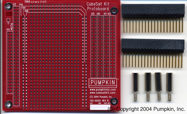
Can I use a PC/104 prototyping card to build a user module?
No. Use a CubeSat Kit Protoboard Kit instead.
Can I use off-the-shelf PC/104 modules in the CubeSat Kit?
Yes. Any PC/104 module can be used. If it's a +5V-only module, it will plug right into the module stack. If it requires other voltages, you'll have to provide them, too.
Can I use PC/104-Plus modules in the CubeSat Kit?
Yes. Any PC/104-Plus module can be used. [2] The Motherboard only has +5V and GND for 8- or 16-bit PC/104 cards. If your PC/104-Plus module requires other voltages, you'll have to provide them, too.
I plan to use a PC/104 SBC running Linux in my CubeSat, and I'm not sure I want / need the Motherboard. Can I remove it to save weight?
The Flight module performs several functions in addition to being the home of the PPM processor. The Remove-Before Flight switch and MHX transceiver are mounted to it. Additionally, there is not enough room to mount a PC/104-sized module in Slot 0. Therefore you should probably keep the Motherboard, and consider assigning it another role (perhaps that of a system supervisor or backup processor) outside of the functionality you plan to implement on your Linux SBC.
Why can't I use the MHX transceiver with a PC/104 module in Slot 1?
There isn't enough room. The PC/104-Plus specification calls for approximately 5mm of clearance below any PC/104-Plus card. PC/104 Cards often have components on the underside of the PCB, too. With the MHX transceiver on the Motherboard, there simply isn't enough room to accommodate components on the underside of the module in Slot 1.
To use the MHX transceiver with PC/104 cards, you could design your own user module for Slot 1, and place your PC/104 module in Slot 2 or higher. Or, you could design your own transceiver to plug into the Motherboard – it would require a substantially lower profile than the MHX transceiver.
Software
What programming background does the CubeSat Kit require?
You should be comfortable programming microcontrollers in C. Some experience with programming paradigms beyond the simple foreground / background loop is helpful.
What kind of software does the CubeSat Kit include?
The PPM processor comes pre-programmed with a basic "skeleton" application that will get you started. It's based on the Salvo RTOS, to make it easier for users to manage the multitude of things the PPM processor will be called upon to do. All application source code (in C) is included.
Additionally, the CubeSat Kit software includes library functions for things like interrupt-driven full-duplex serial communications. These functions will help you get up and running very quickly.
What are the advantages of this RTOS-based software approach?
RTOS-based programming is one of the dominant programming paradigms for embedded programming. The Internet is full of information on this subject. Because Pumpkin's (http://www.pumpkininc.com/) Salvo RTOS is an event-driven RTOS, you will be able to minimize power consumption while maximizing functionality in the PPM processor.
How do I interface to the USB port?
You'll need to use the CubeSat Kit USB drivers. You can use the USB port as a simple terminal interface to the PPM processor, or you can write your own software in the PPM processor and/or the host side to do things like serial bootloaders, etc.
[1] 7.3728MHz for PPM A1|A2|A3, does not include power required by the transceiver.
[2] Physical packaging issues dictate that a user module can connect to the PC/104 bus, and to either the PC/104-Plus bus or the CubeSat System Bus, but not both.